
 English
 Spanish
 French
 German
 Italian
 Chinese (Simplified)
 Japanese
 Korean
 Arabic
 Portuguese
Impeller
Impeller is a crucial component that produces compressed air while rotating quickly. It was designed using more than 10 years of axial/centrifugal compressor development experience in the aerospace industry to maximize the machine's overall efficiency.
Materials- Al Alloy, SUS (option), Titanium (option)
Production Methods
The impeller is produced by the high-speed turbo equipment using forged aluminium alloy, which is machined with a 5-axis CNC machine. Due to the low tolerance of 1/1000mm, the quality of execution is extremely accurate regardless of size. It makes it possible to create high-efficiency impellers. Additionally, the impeller and casing have a strong anodizing coating to increase their endurance and corrosion resistance.
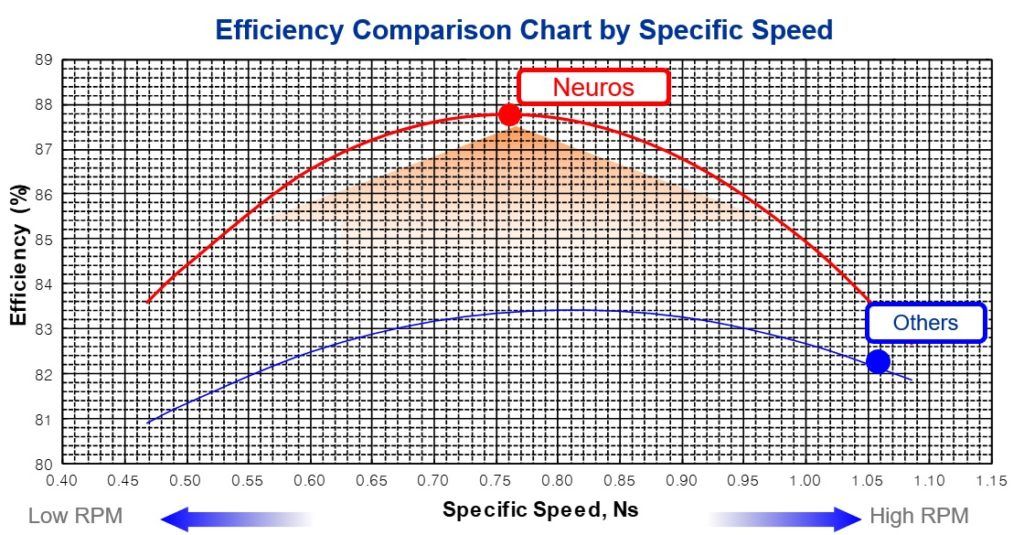
Specific Speed and Efficiency
- When designing an impeller, the specific speed criterion is used to calculate the RPM that will produce the best efficiency at the specified pressure and air flow. Based on the knowledge gained during the advancement of aerospace technology, Neuros used the ideal specific speed, maximizing the impeller's efficiency.
- High RPM: Shorter life and increased heat generation in the motor and inverter.
- Low RPM: Costs and size are rising.
PMSM
PMSM (Permanent Magnet Synchronous Motor) self-developed for high-speed operation: Number 10-0572849
- High and low efficiency losses occur when speed is reduced.
- provides superior speed control
- paired with a sinus filter for little heat production
Production Methods
- By removing the gearbox and lubrication system, direct linkage between the PMSM's rotor and impeller reduced power transfer loss.
- created a lightweight product with a minimal footprint.
Specifications
- Output Power: 30 ~ 330 hp
- Rotational Speed: 10,000 ~ 100,000 rpm
- Efficiency and Power Factor: 95 %
- Number of Poles: 2
- Insulation: H Class (180)
- Cooling: Air + (Water)
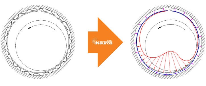
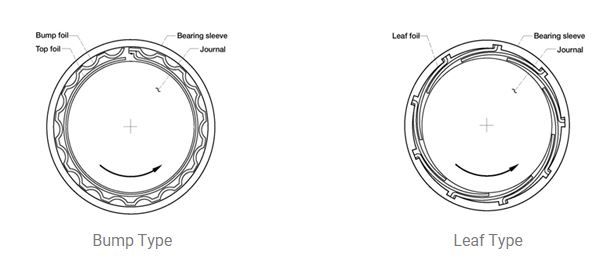
Air Bearing
A non-contact compliant bearing called an air bearing produces an air film on its own as a result of a hydrodynamic interaction between a viscous fluid and a foil structure inside of a revolving sleeve or disc. Based on the foil configuration, they are divided into bump type and leaf type.
Principle
A tiny layer of air forms a cushion between the shaft and the bearing surface as the rotor speeds up.
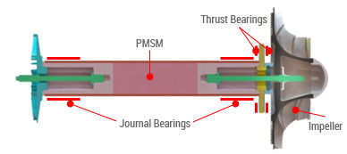
Configuration
- Bump type two journal bearings + two thrust bearings
- Journal Bearing: Rotor Weight, Unbalance Load, Instability Workability
- Thrust Bearing: Thrust Load, Tip Clearance Control, Power Loss Performance
Features
ACM/ECS engines are already using the cutting-edge Neuros air bearing technology, and its dependability has been confirmed. In contrast to conventional blowers, non-contact air bearing achieves 100% oil-free operation by removing the lubrication system. Air bearing also has a high level of durability and ease of maintenance due to its basic structural design. Additionally, it is an environmentally benign technology that achieves noise levels below 85 dB(A) and very low vibration of less than 1/5 when compared to a traditional blower without the use of specific foundations.
Comparison with other bearings
|
Bearing |
Rolling Element Bearing |
Air Bearing |
Fluid Film Bearing |
|
Advantages |
Small |
High Speed |
Long Life |
|
Disadvantages |
Noisy |
Low Load |
Complex |
|
Applications |
Aero Engine |
ACM |
Industrial
Machine |
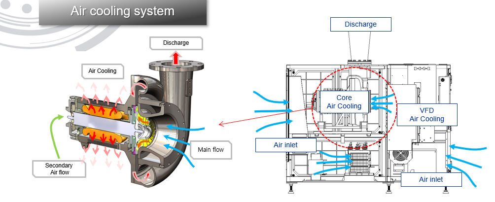
Air Cooling System
Self-cooling system that uses suction air to cool a motor, a VFD, other electrical components, and mechanical parts
- Suction air is a novel method of motor cooling (patent number 10-0572850)
- No requirement for a separate cooling apparatus like an exhaust fan
Maintaining a comfortable work environment and having no adverse effects on the environment requires an air-cooling system without heat emission to the blower room.
USHA NEUROS TURBO LLP
GST : 24AAFFU4590G1Z2
GST : 24AAFFU4590G1Z2
Contact Us
- Survey No.70 Po. Bhayla, Bavla-Bagodara Highway, Bavla,Ahmedabad - 382220, Gujarat, India
- Phone :08045813602
- Mr. Shubham Kumar (Manager)
- Mobile :08045813602
- Send Inquiry
Our Products

USHA NEUROS TURBO LLP
All Rights Reserved.(Terms of Use)
Developed and Managed by Infocom Network Private Limited.
Developed and Managed by Infocom Network Private Limited.
